- What is the transformer?
the transformer is an electromagnetic device there is no rotating part. which is transfer te electrical energy from one circuit to another circuit without changes in Frequency & by step and step down the voltage and current. the transformer can transfer power such as AC and DC. but now a day AC transformer is using than DC transformer due to some of the criteria.

There are three primary types of voltage transformers (VT): electromagnetic, capacitor, and optical. The electromagnetic voltage transformer is a wire-wound transformer. The capacitor voltage transformer uses a capacitance potential divider and is used at higher voltages due to a lower cost than an electromagnetic VT.
- PRINCIPLE OF OPERATION
An alternating current applied to the primary winding induces an alternating magnetic flux in the iron core. Most of this flux stays within the core and only a small percentage of it travels through the air. The alternating magnetic flux in the iron core then links the turns of the secondary windings inducing a voltage. This all follows from Faraday's law of induction. This explains why the primary has a voltage, and the secondary has a voltage, yet there is no interconnection between them.
Overall, a transformer carries the below operations:
Transfer of electrical energy from circuit to another
Transfer of electrical power through electromagnetic induction
Electric power transfer without any change in frequency
Two circuits are linked with mutual induction

The figure shows the formation of magnetic flux lines around a current-carrying wire. The normal of the plane containing the flux lines are parallel to normal of a cross-section of a wire.

- EMF Equation of Transformer
N1 – number of turns in primary.
N2 – number of turns in secondary.
Φm – maximum flux in weber (Wb).
T – time period. Time is taken for 1 cycle.
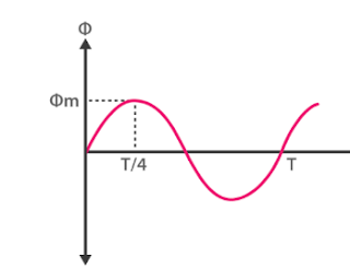
The flux formed is a sinusoidal wave. It rises to a maximum value Φm and decreases to negative maximum Φm. So, flux reaches a maximum in one-quarter of a cycle. The time taken is equal to T/4.
Average rate of change of flux = Φm/(T/4) = 4*fΦm
Where f = frequency
T = 1/f
Induced emf per turn = rate of change of flux per turn
Form factor = rms value / average value
Rms value = 1.11 * (4*fΦm) = 4.44 fΦm [form factor of sine wave is 1.11]
RMS value of emf induced in winding = RMS value of emf per turn * no of turns
Primary Winding
Rms value of induced emf = E1 = 4.44 fΦm * N1
Secondary winding:
Rms value of induced emf = E2 = 4.44 fΦm * N2
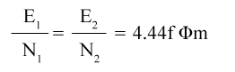
This is the emf equation of the transformer.
For an ideal transformer at no load condition,
E1 = supply voltage on the primary winding.
E2 = terminal voltage (theoretical or calculated) on the secondary winding.
Voltage Transformation Ratio

K is called the voltage transformation ratio, which is a constant.
Case1: if N2 > N1, K>1 it is called a step-up transformer.
Case 2: if N2< N1, K<1 it is called a step-down transformer.
- BASIC PART OF TRANSFORMER
These are the basic components of a transformer.
Laminated core
Windings
Insulating materials
Transformer oil
Tap changer
Oil Conservator
Breather
Cooling tubes
Buchholz Relay
Explosion vent
if you Don't have the patience to read? Watch the video.
- WHY WE USE TRANSFORMERS
TO DISTRIBUTE POWER AT HIGH VOLTAGE.
It is more cost-effective to distribute power at higher voltages since power dissipation (loss) in a resistive load is given by the square of the current times the resistance of the wire. It is best to use the lowest possible current and thus the largest potential difference (voltage). A typical transformer will take in the input of 480 or 600 volts and step the voltage down to 240 volts for some motors, or 120 volts for other applications like consumer products, lights, etc. The overall result is better voltage regulation, minimized line loss and reduced wiring costs.
TO ELIMINATE DOUBLE WIRING.
For maximum safety, 120-volt lighting and control circuits may be obtained from 240, 480, or 600-volt power circuits by installing transformers at the most convenient location to the load. This eliminates separate circuits and independent metering for power and often results in substantial savings.
TO INSULATE CIRCUITS.
Installing transformers provides a means of subdividing circuits to accommodate independent demand. Connecting to a 3 phase, 480-volt circuit a transformer can provide
120/240 volt 3 wire single phase load:
120-volt single-phase load:
240-volt single-phase load.
Transformers permit grounding of each low voltage circuit.
- Transformer Types
Transformers are used in various fields like power generation grid, distribution sector, transmission and electric energy consumption. There are various types of transformers which are classified based on the following factors;
Working voltage range.
The medium used in the core.
Winding arrangement.
Installation location.
Based on Voltage Levels
Commonly used transformer type, depending upon voltage they are classified as:
Step-up Transformer: They are used between the power generator and the power grid. The secondary output voltage is higher than the input voltage.
Step down Transformer: These transformers are used to convert high voltage primary supply to low voltage secondary output.
Based on the Medium of Core Used
In a transformer, we will find different types of cores that are used.
Air core Transformer: The flux linkage between primary and secondary winding is through the air. The coil or windings wound on the non-magnetic strip.
Iron core Transformer: Windings are wound on multiple iron plates stacked together, which provides a perfect linkage path to generate flux.
Based on the Winding Arrangement
Autotransformer: It will have only one winding wound over a laminated core. The primary and secondary share the same coil. Auto also means “self” in language Greek.
Based on Install Location
Power Transformer: It is used at power generation stations as they are suitable for high voltage application
Distribution Transformer: Mostly used at distribution lanes in domestic purposes. They are designed for carrying low voltages. It is very easy to install and characterized by low magnetic losses.
Measurement Transformers: These are further classified. They are mainly used for measuring voltage, current, power.
Protection Transformers: They are used for component protection purposes. In circuits, some components must be protected from voltage fluctuation etc. protection transformers ensure component protection.
This blog give me very much information about transformer, thanks for sharing this.👍
ReplyDelete👍
ReplyDeleteParaflex is the Best brand of wires and cable in India. Today Paraflex is the most favourite brand because it provides high-quality products at affordable prices and available all over India.
ReplyDelete